Like runway markings, taxiway markings are standardized throughout the world.
A quick look at the layout of Atlanta Hartsfield International Airport demonstrates the need for clear and consistent markings and signs to allow flight crews to navigate to and from any one of the runways.
It is important that pilots understand taxiway and runway markings and signs.
Many airlines require pilots to be familiar with destination airports, meaning that a pilot who has not flown into an airport such as Atlanta International must first fly with a pilot who is already familiar with the airport.
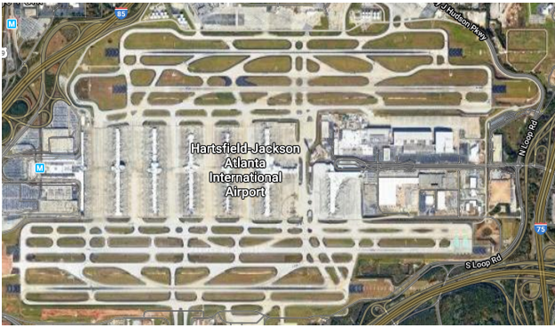
The angular taxiways adjoining the runways (Figure 1) allow aircraft to exit the runway at slightly higher speeds to expedite traffic, rather than having to slow to make a hard-ninety-degree turn.
Taxiways are the routes aircraft travel from and to passenger terminals and runways.
Air Traffic Controllers expect pilots to be familiar with the layout of the airport so that they can give the crew taxi instructions and be confident that they will follow the instructions correctly.
Each taxiway is marked by painted lines on the pavement as well as signs adjacent to the taxiways at key locations such as taxiway intersections and runways.
Related Article – 12 Runway Markings Explained By A Pilot
General Taxiway Markings
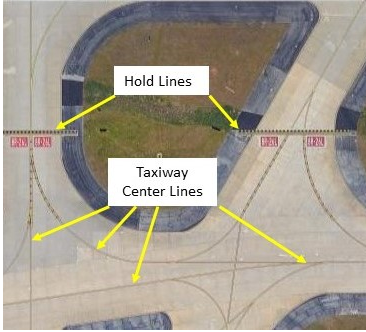
All taxiways have yellow centerline markings and hold position markings wherever the taxiway intersects a runway.
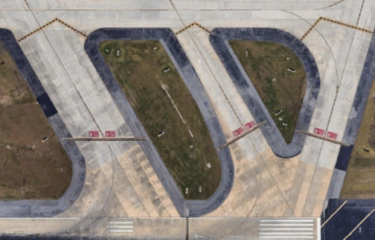
Unless cleared by Air Traffic Control (ATC, either tower control or ground control), aircraft must stop at all runway hold positions and hold until cleared to proceed (Figure 2).
1. Normal Centerline
The continuous yellow taxiway centerline, typically six to twelve inches wide; provides visual guidance along the center of the taxiway.
Ideally, the aircraft nosewheel(s) should be kept centered on this line during taxi; pilots must still be vigilant for other aircraft, vehicles, and potential hazards.
2. Enhanced Centerline
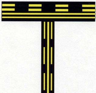 At some, mostly larger commercial airports, an enhanced taxiway centerline is used to alert pilots they are approaching a runway hold line.
The enhanced center line consists of three parallel lines—the center line is a solid line; the parallel lines are dashed (Figure 3).
Enhanced centerlines start no more than 150 feet from the runway hold marker.
3. Surface Painted Location Sign
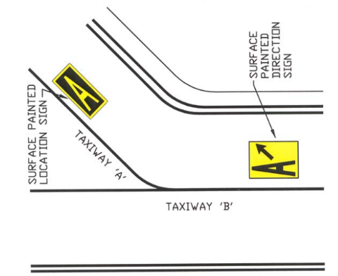
Surface painted location signs are used to supplement location signs located alongside a taxiway.
Surface painted location signs have a yellow taxiway identifier letter on a black background (Figure 4).
4. Surface Painted Direction Sign
Surface painted direction signs are located on the right side of the centerline indicating a turn onto the identified taxiway.
Surface painted direction signs are yellow with a black lettering (Figure 4).
5. Surface Painted Holding Direction Sign
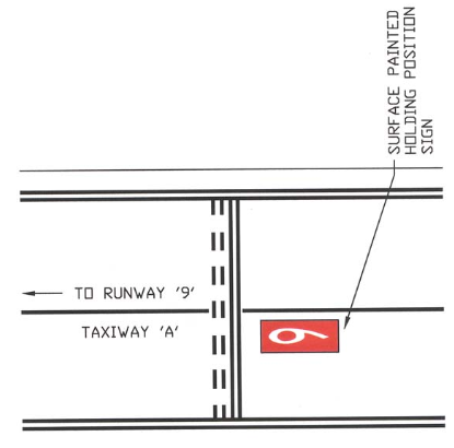
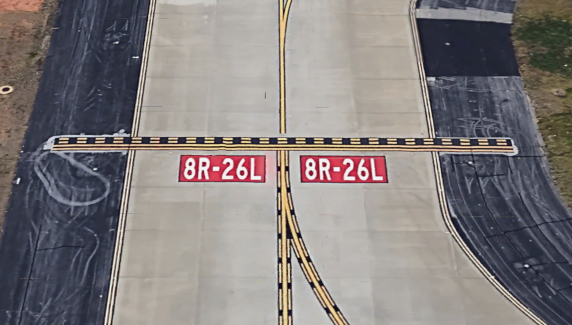
Surface painted taxiway holding direction signs have a red background with white lettering that identify the runway the taxiway is approaching.
The surface painted holding position sign provides additional warning, especially where a taxiway crosses a busy runway and on taxiways 200 feet or more wide.
The runway number sign has a red background with white lettering (Figure 5.)
Related Article – 5 Best Low Time Pilot Jobs With 250 Hours
6. Surface Painted Holding Position Signs
Figure 6 shows an overview of various surface painted holding position signs.
Note that there may be hold signs on taxiways beyond the ends of runways—these require aircraft to wait for aircraft approaching the runway to land.
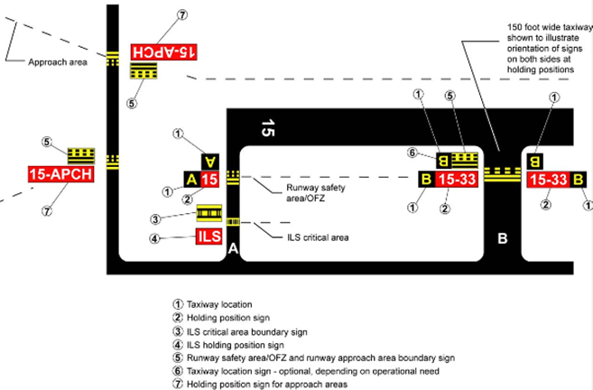
- The letters (A and B in the example) identify the taxiways. Letters are seen as right side up from the pilot’s position when approaching the runway.
- The holding position sign is located adjacent to the holding line that indicates the edge of the runway safety zone.
- Aircraft are to hold at the ILS critical area boundary holding lines when ILS approaches are in progress.
- At larger airports, a red ILS sign may be posted adjacent to the surface ILS holding boundary sign.
- This is an approach area holding line: even though the taxiway does not cross the runway, low flying aircraft approaching to land on Runway 15 are to be expected–hold for ATC clearance before continuing to taxi.
- Taxiway identification sign for landing aircraft on the runway.
- Red runway identifier signs may be located adjacent to the runway hold line.
7. Guidance-to-Runway Signs
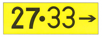
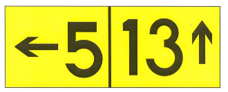
At key points along a taxiway, airports may post guidance signs to runways.
Figure 7-A indicates that this taxiway leads to both runway 27 and 33 (Figure 7-A).
Figure 7-B shows that the pilot should turn left to go to Runway 5 or continue straight ahead to go to Runway 13.
8. Frequency Change Signs
At large airports, Ground Control duties may be divided among two or more areas, each with its own controller.
“Frequency Change” signs, usually associated with a stop sign, will be posted along taxiways indicating that the ground control frequency should be changed at that point.
Related Article – Airline Transport Pilot Certificate: 4 Things You Need To Know
Taxiway Edge Markings
Taxiway edge markings define the lateral limits of the taxiway: there are two types of edge markings.
9. Continuous Edge Markings
Often blacktop areas are used to stabilize the earth along taxiways to (1) prevent jet blast from blowing dirt and debris onto the pavement or toward aircraft behind them or (2) to indicate areas that will not support an aircraft.
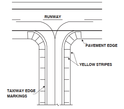
Solid, continuous (unbroken) six-inch wide, double yellow lines indicate that the edge markings should not be crossed.
Yellow stripes may be painted on stabilized areas to alert pilots that these areas are not intended to support aircraft (Figures 8).
10. Dashed Edge Markings
These lines define the edge of the taxiway, but allow aircraft to cross them as necessary, for example, to turn onto a parking apron, etc.
Dashed taxiway edge markings consist of a pair of broken double yellow lines, with each line being at least 6 inches in width, spaced 6 inches apart.
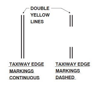
These lines are 15 feet long; the spaces, or gaps, between the yellow pairs are 25 feet (Figure 9).
11. Geographic Position Markings
Geographic Position Markings are used to identify the location of taxiing aircraft during low visibility operations (RVR less than 1200 feet).
They are positioned to the left of the taxiway centerline in the direction of taxiing (Figure 10).
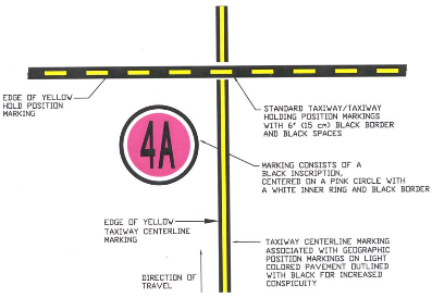
The geographic position marking, a circle with black and white outer rings and a pink circle in the middle.
It is designated with either a number or a number and letter; for example, ATC may request reporting when your aircraft is at “Position Marking A4” to confirm your position under poor visibility conditions.
12. Runway Hold Markers
There are two types of Hold markings (Figure 11):
(1) The first hold line (Detail 1, Figure 11) may be used when the airport is operating under VFR conditions and landing aircraft are NOT relying on the ILS for landing guidance.
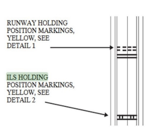
Pilots must stop before the hold lines unless cleared by ATC to cross or turn onto the runway.
Aircraft exiting the runway do not have to stop at the hold lines.
At uncontrolled airports, pilots are expected to stop before the hold line until the runway is clear to cross, or to turn onto, the runway.
Runway holding position markings may be found in three locations: (1) Runway holding position markings on taxiways, (2) on runways where runways cross; and (3) taxiways located in runway approach areas.
(2) The second hold line is the ILS Holding Position Markings (Detail 2, Figure 11) used when aircraft are actively using the ILS for landing guidance (aircraft too close to the runway can interfere with the ILS guidance signal).
Related Article – Instrument Proficiency Check (IPC): 3 Things You Need To Know
13. Stop Bar Lights
Busy commercial airports may have stop bar lights installed at the hold line.
They are used to confirm ATC clearance to enter or cross the active runway in low visibility conditions (below 1,200 ft Runway Visual Range).
The stop bar consists of a row of red, unidirectional, steady−burning, in−pavement lights across the entire taxiway at the runway holding position, plus elevated steady−burning red lights on each side (Figure 12).
A controlled stop bar is operated in conjunction with the taxiway centerline lead−on lights which extend from the stop bar toward the runway.
Following ATC clearance to proceed, the stop bar is turned off and the lead−on lights are turned on. The stop bar and lead−on lights are automatically reset by a sensor or back-up timer.
14. Direction Sign for Runway Exit
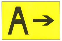
Direction signs are normally located on the left side of the taxiway, prior to the intersection.
When used on a runway to indicate an exit, the sign is located on the same side of the runway as the exit (Figure 13 shows a direction sign used to indicate a runway exit to taxiway A).
Summary
Navigating airport taxiways can seem confusing at first, but with just a little study, it becomes quite logical.
When flying into an airport for the first time—especially busy controlled airports—it is a good idea to go with another pilot who is familiar with the layout.
Still, understanding the signs and listening to the controller’s instructions, navigating an airport is usually not difficult.
At larger airports, controllers may provide a pilot with a sequence of taxiways to follow; it is a good idea, if possible, to quickly jot down the instructions.
_____
Note: All graphics used in the article were taken from the current Airman’s Information Manual.
Aerial views of Atlanta Hartsfield airport were captured from Google Maps and Google Earth.


No airplane should be allowed to hold anywhere on an active runway. There is too much potential for collision due to human error or poor visibility, as we saw at Haneda. The gain in efficiency is not worth the cost in human lives.