There are only a few non-engine indicators that an airplane really needs for VFR flight.
A compass to see where you’re headed, an altimeter to see how high up you are, and an airspeed indicator to tell how fast you are going.
Planes are designed to operate at certain speeds, and it’s important to be able to know if you are exceeding or going under the limits.
If you go too slow, the plane will stall, but if you go too fast, you risk structural failure.
Other airplane configurations, like retractable gears down and flaps deployed, change some of the minimum and maximum allowable speeds.
Therefore, it is not just important, but essential, for a plane to have a working airspeed indicator.
1. What is an Airspeed Indicator?
An Airspeed Indicator, or ASI, is a differential pressure gauge that measures dynamic pressure of the air through which the aircraft is flying.
It displays the aircraft’s speed, typically in nautical miles per hour (knots), but sometimes in miles per hour (MPH) or, occasionally, both.
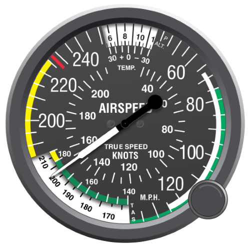
It uses a single needle to indicate air speed, 0 starting at the 12 o’clock position, and sweeping clockwise.
The face has several different colored arcs, which indicate different speed ranges, and will be explained below.
Related Article – Aircraft Altimeters Explained
2. How does an Airspeed Indicator work?
An Airspeed Indicator is a differential pressure gauge that uses both the static port and the pitot tube.
It is the one instrument which uses both the pitot tube and static port in conjunction.
As the aircraft moves through the air, the airstream slams against the pitot tube, causing an increase in dynamic pressure, also known as the ram air effect.
The high-pressure air from the pitot tube is fed into a diaphragm inside the Airspeed Indicator, which is surrounded by lower pressure air from the static port.
The diaphragm is attached to several mechanical linkages which translate the movement of the diaphragm into radial motion of the Airspeed Indicator needle.
3. Airspeed Indicator Colors Explained
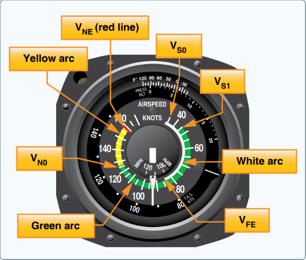
On the face of the Airspeed Indicator are several colored arcs, white, green, yellow, and a single red line.
See the diagram below for the bigger picture.

White
The white arc indicates the flaps operating range. The lower limit is the full flaps, gear extended stalling speed, while the upper limit is the maximum speed with flaps extended.
Landings and departures are generally flown within the limits of the white arc.
Green
The green arc indicates the normal operating range of the aircraft. Most flying occurs within this arc.
The bottom of the green arc indicates the stalling speed of the aircraft in a specified configuration.
This generally means it is the power off stall speed at maximum takeoff weight in a clean configuration, which means gears up (if applicable) and flaps retracted.
The upper limit of the green arc is the maximum structural cruising speed. It is only safe to exceed this limit in smooth air.
Yellow
The yellow arc is the caution zone. Only fly within this range in smooth air and with caution.
Red
The red line at the top of the yellow arc is the never exceed speed.
If a pilot operates above this speed, structural damage or a catastrophic failure can occur.
4. Two Types of Airspeed Indicators
There are two types of Airspeed Indicators commonly used on aircraft, the classic “steam gauge” that has been described, and the glass panel indicator, part of the Electronic Flight Display
Classic “Steam Gauge”

Classic Steam Gauge indicators are the ones that have been discussed, with a round face and several different colored arcs indicating different airspeed limits.
Glass Panel
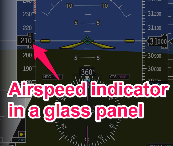
A Glass Panel, or Electronic Flight Display, is a digital, screen-based display that combines all of the functions of the classic, round faced “steam gauges” into one compact package.
On an EFD, the airspeed is normally displayed to the left of the attitude indicator, in a vertical box called the Airspeed Tape.

It only displays part of the numbers, but has a fixed arrow which indicates the current airspeed reading.
All of the previously discussed colors are also displayed within the airspeed tape.
EFD’s are generally more accurate and reliable than steam gauges, but because the screen itself is a point of failure, a backup steam gauge Airspeed Indicator is always included with the installation.
Related Article – Biennial Flight Review Explained
5. What are some common Airspeed Indicator errors?
The indicated airspeed is not always the actual speed of the aircraft.
There are different kinds of airspeeds which need to be accounted for, as well as installation or instrument errors.
A blockage in either the pitot tube, the static port, or both, can also cause errors, which are discussed below.
6. Types of Airspeed
Indicated Airspeed (IAS) – This is the airspeed read directly off of the gauge, uncorrected for air density, instrument error, or installation error.
The airspeeds indicated in the Pilot’s Operating Handbook are based off of the Indicated Airspeed, and generally don’t change with altitude or temperature.
Calibrated Airspeed (CAS) – This is Indicated Airspeed corrected for instrument and installation errors.
True Airspeed (TAS) – Calibrated Airspeed corrected for nonstandard pressure and temperature.
Because density decreases with increased altitude, TAS increases compared to CAS as altitude increases.
The amount of variance can be computed using a flight computer, or simply add 2 percent to the CAS for every 1000ft of altitude.
Blocked Pitot System
The pitot tube has two ports, the entry, a drain hole, along with the connection to the Airspeed Indicator.
If the pitot tube becomes blocked, but the drain hole remains open, remaining air inside the system vents through the drain, becoming equal to the static pressure.
When this happens, the Airspeed Indicator will read zero, as there is no differential between static and dynamic pressure.
If both the pitot tube and the drain hole become clogged, it will remain the same from the time the blockage occurred.
If the static port remains unblocked, it will change depending on height, indicating faster if at a higher altitude, and indicating lower if at a lower altitude.
If both the pitot/drain and the static port become blocked at the same time, the Airspeed Indicator will remain stuck on the indication at the time of the blockage.
However, because there will be zero pressure differential, there will be no change at all in the indicated reading until the blockages are cleared.
Blocked Static System
A blocked Static System is a more critical problem than a blocked Pitot System because the Airspeed Indicator, Vertical Speed Indicator, and Altimeter all use the Static System.
If the static port becomes blocked, the Airspeed Indicator remains operational, but is inaccurate.
Because a blocked static port traps the static pressure at the density altitude of the blockage, indicated airspeeds will vary based on altitude.
If a plane with a blocked static port climbs, the Airspeed Indicator will read low, and if the plane descends, the Airspeed Indicator will read high.
Certain aircraft are equipped with an alternate static source located inside the cockpit.
Should a pilot suspect a clogged static port, the alternate static source should be used.
Conclusion
The Airspeed Indicator is a critical component for every aircraft.
In addition to telling the pilot how fast the plane is going, it also shows, via colored arcs, different operating speeds depending on configuration.
An Airspeed Indicator operates using a pressure differential, taking a static pressure reading from the static port, and a dynamic pressure reading from the pitot tube.
Generally, Airspeed Indicators are fairly accurate, but may have small errors based on installation/indicator errors, as well as temperature and density.
Occasionally, the pitot/static system can become clogged, rendering the Airspeed Indicator inaccurate.
Knowing and understanding how an Airspeed Indicator reads during a blockage is critical for safety.
References
https://www.faa.gov/regulations_policies/handbooks_manuals/aviation/phak/media/10_phak_ch8.pdf

